

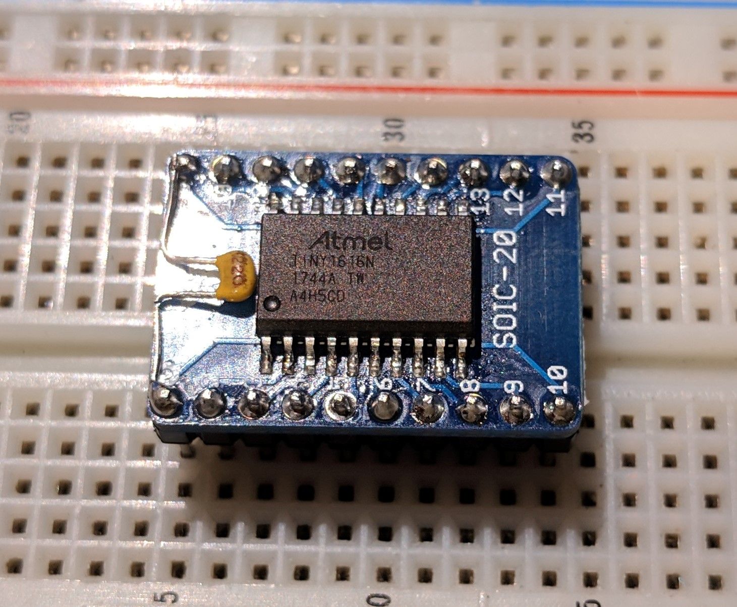
Recently while browsing Digikey, I came across a new-to-me AVR microcontroller, the ATtiny1616 (Datasheet here). It has impressive specs and an extremely reasonable price (less than $1.50CAD in single quantities). But, there are a few caveats to contend with. It is only available in SMD packages which can make prototyping a little bit tricky, and bigger than that, it doesn't use the classic AVRISP programmer.
This micro came out after the Atmel-Microchip merger and is part of the new tinyAVR 1-Series. This means that it has a few key differences to AVR's that you may be familiar with. The most significant to the actual process of developing with it is your AVRISP programmer is unable to program it. It uses a new programming interface called UPDI which stands for Unified Program and Debug Interface. The lowest-cost official programmer for it seems to be the Atmel-ICE which costs over $150. Fortunatley there is a cheaper, easier solution that you probably have the parts for - pyupdi.
pyupdi is a is a driver written in python that lets you turn a simple usb to serial adapter into a UPDI programmer using a single resistor. To set it up, all you need to do is connect the RX pin of the adapter to the UPDI pin on the micro and the TX pin to that through a 4.7k resistor. Then just use the program on your computer.
The other thing you may have to deal with if you choose to use these new microcontrollers are the SMD packages. Fortunately, SOIC packages are relativley easy to hand-solder and breakout boards can be had for cheap on Digikey or anywhere else.
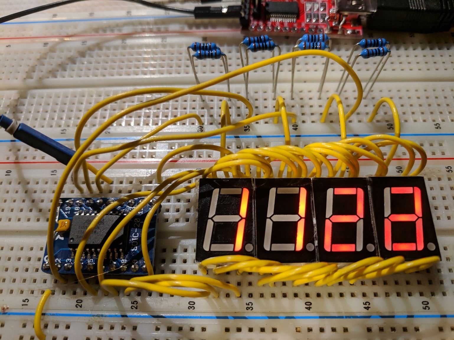
As a simple hello-world project to get used to the new device, I chose to use some seven segment displays I recently got. I wanted to try multiplexing and this was the perfect opportunity. I built up the following circuit and then got to programming.

The seven segment displays are common-cathode to each of the commons is connected to an I/O pin on the micro. Then each of the segment pins are connected to each display ans well as seven more I/Os. Ideally, each segment pin would get a resistor instead of resistors on the common cathode but i just wanted to keep the wring clean so I opted for this setup. Because of this, the brightness depends on how many segments are turned on.
The code is relatively simple, just increasing the number displayed. It can be found below:
#define  F_CPU 3300000
#include <avr/io.h>
#include <util/delay.h>

int main(void)
{
	PORTB.DIR = 0xFF;
	PORTA.DIR = 0xFF;
	PORTA.OUT = 0x00;

	char SegA[] = {0x80, 0x80, 0x00, 0x00, 0x00, 0x00, 0x00, 0x80, 0x00, 0x00, 0x00, 0x00, 0x80, 0x00, 0x00, 0x00};
	char SegB[] = {0xC0, 0xF9, 0xE4, 0xF0, 0xD9, 0xD2, 0xC2, 0xF8, 0xC0, 0xD8, 0xC8, 0xC3, 0xC6, 0xE1, 0xC6, 0xCE};

	int count = 0;

	int DispA = 0;
	int DispB = 0;
	int DispC = 0;
	int DispD = 0;

    while (1) {
		count ++;

		PORTA.OUT = (PORTA.OUT & ~0b10000000) | (SegA[DispA] & 0b10000000);
		PORTB.OUT = (PORTB.OUT & ~0b00111111) | (SegB[DispA] & 0b00111111);
		PORTA.OUT |= (1 << 1);
		_delay_us(30);
		PORTA.OUT &= ~(1 << 1);

		PORTA.OUT = (PORTA.OUT & ~0b10000000) | (SegA[DispB] & 0b10000000);
		PORTB.OUT = (PORTB.OUT & ~0b00111111) | (SegB[DispB] & 0b00111111);
		PORTA.OUT |= (1 << 2);
		_delay_us(30);
		PORTA.OUT &= ~(1 << 2);

		PORTA.OUT = (PORTA.OUT & ~0b10000000) | (SegA[DispC] & 0b10000000);
		PORTB.OUT = (PORTB.OUT & ~0b00111111) | (SegB[DispC] & 0b00111111);
		PORTA.OUT |= (1 << 3);
		_delay_us(30);
		PORTA.OUT &= ~(1 << 3);

		PORTA.OUT = (PORTA.OUT & ~0b10000000) | (SegA[DispD] & 0b10000000);
		PORTB.OUT = (PORTB.OUT & ~0b00111111) | (SegB[DispD] & 0b00111111);
		PORTA.OUT |= (1 << 4);
		_delay_us(30);
		PORTA.OUT &= ~(1 << 4);


		if (count >= 25) {
			count = 0;
			DispD++;
			if (DispD > 9) {
				DispC++;
				DispD = 0;
				if (DispC > 9) {
					DispB++;
					DispC = 0;
					DispD = 0;
					if (DispB > 9) {
						DispA++;
						DispB = 0;
						DispC = 0;
						DispD = 0;
						if (DispA > 9) {
							DispA = 0;
							DispB = 0;
							DispC = 0;
							DispD = 0;
						}
					}
				}
			}
		}
	}
}
If you are using Atmel studio, you can set the custom programming command to this, changing the path and COM port to however your system is set up. path\to\python.exe path\to\pyupdi.py -d tiny1616 -c COM# -f $(OutputDirectory)$(OutputFileName).hex This way pressing Start Without Debugging will build and upload your program. More details here.
To program from the command line, use the command python path\to\pyupdi.py -d tiny1616 -c COMX -f yourfile.hex -v. If everything is hooked up correctly, you should be all set!
Troubleshooting
If you are having some issues, try going through the following:
- Ensure the ground of the adapter is connected to the ground of your circuit.
- Make sure you have all python dependencies installed (pip install intelhex pylint pyserial).
- The voltage of your serial adapter should be the same as your circuit.
- Nothing else can be using the COM port.
- Python 3 should work but some people have had issues. Try 2.7.
- Make sure you don't disable the UPDI pin with fuses. You'll need a high-voltage programmer (Big $$$) to recover your chip.
- If you are on Linux, your COM port will likely be /dev/tty<something>. Make sure your user is the group for tty access (usually
uucp), and test out your serial connection before trying pyupdi. If all is well both with your software and hardware (4.7K resistor), any characters you send should be echoed right back.
Helpful Links
Email me with any suggestions or questions!